One of the most important aspects when setting up an RV site is an efficient power supply that not only is safe but also provides proper electricity. From whether you are an electrician, a DIY enthusiast, or an RVer, understanding power pedestal wiring is one of the key aspects to providing a reliable power source to an RV. This article will explain the wiring diagrams and schematics necessary for the installation of RV power pedestals, providing a sense of clear clarity and how best to start by understanding the task. So, from understanding the status of the power pedestal components to negotiating complex circuitry, this article will equip you with the knowledge to make the entire installation seamless and safe. Check to see whether we successively unfold axioms; we might end up rendering difficult even schematics a simplistic and easy to grasp in the end.
Understanding Power Pedestal Basics

What is a Power Pedestal?
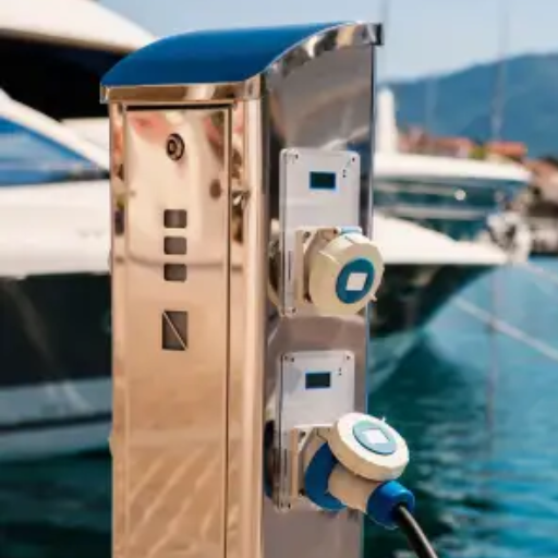
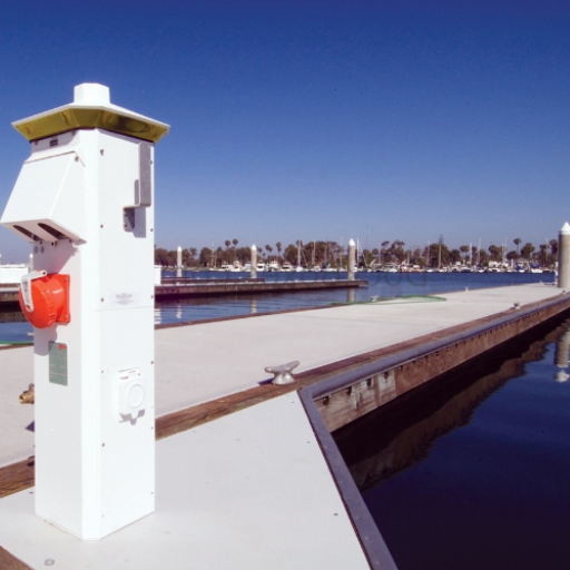
A Power Pedestal is a utility device often deployed to distribute electrical power in a safe and efficient manner around outdoor locations. They are mostly found in areas such as marinas, RV parks, or campgrounds, where mobile equipment is required or temporary setups are required to be hooked into electricity. They are the point of central connection to the electrical power for the various users, and often accommodate more than one person being able to connect the same line.
The function of a power pedestal is to supply power to the electrical stuff while protecting the life of the users with various security devices-it naturally includes circuit breakers, ground fault protection, and a weather-proof enclosure in order to deter conditions such as electrical overload, or moisture ingression. Specific testimony of the use cylinder of electricity into various configurations having with variable voltage levels for compatibility to all kinds of equipment.
Apart from basic power connections, modern power pedestals offer integrated features like lights, energy metering for tracking consumption, and maybe connected water (in some cases). Power pedestals are designed so as to endure outdoor weather and are habitually engineered towards longevity in order to achieve their main objective of being the primary infrastructure accommodating secure and reliable power at all times, quite necessary for many temporary or longer-term usages.
Components of a Power Pedestal
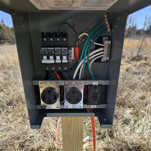
A power pedestal contains a number of important components that help ensure safe and efficient electrical power distribution for outdoor areas. Many of these components are prevalent in modern power pedestals.
Power Sockets:
There are usually space of electrical outlets with various voltages and amperages on power pedestals. However, most are for 120 and 240 V. Sockets are generally bought to comply with international electrical Code standards to ensure safety and compatibility. For example, you can see that these power pedestals generally include an assortment of receptacles for 30A or 50 amp plugs, intended for temporary use for RVs, boats or perhaps other such temporary means for supplying power.
Protection for Circuits:
Integrated circuit breakers and ground fault circuit interrupters (GFCIs) remain essential elements in the domain of user safety. They offer protection against short circuits, overloads, and ground faults, thus minimizing any risk of accidents or damage to the equipment in power lines. As per the NEC standards, for many installations, it is imperative that these components are included.
Energy Metering Tools:
Real-time energy metering systems are typical features of high-end power poles that enable users to keep track of electricity usage. The most common variant comprises digital meters that provide real-time usage data to be used for billing and energy-management purposes. Also, smart energy meters, which can be connected with Wi-Fi or a cellular network, are increasingly being installed.
Lighting:
LED lights significantly help visibility and safety to a certain degree for docks on marinas and RV parks. These energy-saving lights are usually daylight or motion controlled to be maximally productive and spare energy.
Water Connection (Optional):
Some power pedestals include a water connection, particularly in marina or RV park applications. The receptacles, therefore, are equipped to withstand the sunlight, moisture, and weather conditions of the marinas.
Enclosure and Durability Features:
The power pedestal is designed with a specific view of harsh environmental conditions. Material such as stainless steel or UV-resistant polycarbonate is commonly used for these enclosures for great durability and resistance to corrosion. Elevated pedestals often carry independent ratings for protection based on environmental severity, with some being considered for aspects like NEMA 3R or IP65 standing strong against water-tight, weather-proof, and dust-resistant.
Connectivity and Smart Features:
The latest power pedestals come with Internet of Things (IoT) capabilities to enable remote monitoring and control. A property manager or facility owner can control lighting, power settings, monitor energy consumption, failure detection, while improving operational efficiency with applications or software interfaces.
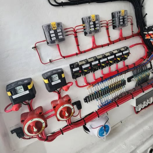
Types of Shore Power Connections
To sail during the day or through the night, boats require shore power connections to transfer electricity from a docking marina to the boat. This is because boats must use their electrical systems, charge batteries, or run appliances without the help of onboard generators. Different types of shore power connections are designed with the sizes and power demand of vessels as well as international standards in mind.
110V/30 Amp Connections:
This type of shore power cable is considered the most common type used for smaller pleasure ships. At 30 amps max, this line could usually feed anything that would keep up your lights, batteries, and small appliances. The drawing of the plugs on the male and female sides complies specifically with NEMA L5-30, ensuring a better, steady connection.
220V/50 Amp Single-Phase:
Considering the much higher electrical use of larger boats, our concern is that a 50-amp service ought to be upgraded for 50 amperes of up to 50 volts. More voltage and current in transmission are offered by this connection design, due to which it is capable of switching really heavy appliances like air conditioners, water heaters, and a home theater system etc. Usually such a connection has maritime application standards according to NEMA SS-2.
100 Amp Three-Phase Connections:
That is, one is in large super-yachts or commercial ships, and those which need more power should have either a 100-amp three-phase system or more depending on their loads. Thus, this delivers a major measure of power across multiple circuits assuring not only stability but efficiency under heavy electrical load, too.
European Standard Connections:
Some of the European marinas run a system of 230V/50Hz, with socket designs subject to International Electrotechnical Commission (IEC) standards like IEC 60309. Boats cruising between countries in different continents can face issues in terms of various differences in the voltage and frequency of each region.
Dynamic Shore Power Technologies:
A consideration of the possible emerging technologies is those endorsed by the dynamic shore power solutions with adjustable voltage systems and frequency converters. This enables ship generators to suit into different standards in ports, meaning a good opportunity for minimizing onboard generators.
Installation Instructions for Power Pedestals

Preparing for Installation
When planning to install power pedestals, it is important to consider a site assessment. It will help identify any prerequisites concerning the installation site and limitations. First and foremost, a location needs to be identified to install power pedestals, which complies with all safety standards and accessibility requirements. Verify the electrical groundwork of a site is suitable in view of the proposed power network of the power supply system, inclusive of the voltage and frequency requirements. Then, it is particularly a good idea to cordon off the installation area properly for the sake of accuracy.
Make the foundation and appropriate components ready after the designated site is inspected. Important signs to ascertain this include stable ground with no obstructions at the site level interfering with installation. Appropriate anchoring systems will ensure the mounts are anchored in place with adequate support. Have necessary tools and devices on standby, including wire components, screws, and connectors to expedite everything. Confirm that materials used for assembly fully comply with local codes and standards.
To secure in place the power pedestal durin installation already in place, following the manufacturer’s instructions. Wire the pedestal in to the power grid using the appropriate wiring methods, securing that all connections are safe, probably insulated. The system should be properly tested for efficient and reliable operation after installation. Get some final inspections from local authorities to ensure compliance in line with safety standards and industry regulations; preparation and timing are the keys to ensuring that a good and safe power pedestal is installed.
Step-by-Step Installation Guide
Prepare the Site for Installation
Choosing a fitting location for the power pedestal installation ensuring that it’s level, stable, and protected from excessive moisture or flooding. Clear the area of debris, check underground utilities with the help of locator services. You’re advised to always assure that the site meets with local building codes and any zoning requirements.
Fix the Pedestal
Fix the pedestal at the location provided on a leveled base on plinths or other suitable foundation or should you be working in firm and stable ground for soil anchoring. The pedestal is to be fixed to a firm end with bolts or concrete with the castle stone section or utilizing anchor bolts discarding all that reveals possible instability of the pedestal from wind or external forces caused maybe by an accident, such as vehicular collision.
Connect Power to The Grid
Establish the connection of the pedestal to the power supply. This should be done in accordance with electrical standards and codes as set forth by the local governing body. The wires run should be well insulated, made tight, and double-checked to prevent any mishaps. Ensure that cable sizes and circuit breakers are correctly sized to meet the power load serviced by the pedestal; otherwise, the pedestal will not work effectively.
Testing
After all connections are made and thoroughly tested, ensure whether the system will work efficiently and stay safe. Verify if the output voltage is fine, if all the electrical supplies function properly, and no heating or malfunctioning equipment is noted during the test.
Final Inspection and Certification
To make sure the system meets expected safety standards and codes, ask a certified electrician or technical representative from the utility to inspect the job. After the tab is rung off for design approval, the power pedestal may be operated as needed. This signifies a safe and sound power source for the systems it was intended to support.
Height and Placement Considerations
The power pedestal should be adjusted to make sure it is at the best possible height while maintaining accessibility and meeting local regulations. The pedestal height may be adjusted depending on how low the pedestal has to be operated safely and out of the reach of potential dangers (like flooding or accumulation of trash). Although the mounting height commonly ranges from 24 to 48 inches from grade, it could be lower and compliance with local codes and environmental factors.
A proper pedestal shall be designed such that the requested purpose is achieved along with safety and efficiency. Of importance is the distance of the utility pedestal from the holder electrical equipment, which reduces cable lengths and therefore voltage drop. The pedestal needs to be shielded from pedestrian traffic and potential vehicular damage while providing safety and reliability at the same time. And the maintenance to be performed on the pedestal should not disrupt the surroundings.
Before commencing with the installation, consultation should be made with some of the most important building codes and utility company guidelines to check for compliance. Additional others may implement further requirements, such as providing particular barriers around the pedestal or grounding procedures, in order to maintain a secure and long-lasting functional installation.
Wiring Diagrams and Schematics

Common Wiring Configurations
The wiring configurations commonly used for installations typically depend on the specific requirements of the device and local electrical codes. The simplest of these setups provide for only a single-phase connection, which, usually, is patronized for residential or light commercial applications. It includes a line wire(hot), a neutral, and sometimes the ground wire for safety purposes; when combined in the proper manner, these ensure a balanced and secure flow of electricity.
For larger or more complex systems, such as those found in industrial settings, commonly used are the three-phase wiring configurations. This design allows them to transfer power over large lengths and is more efficient in terms of energy consumption. A three-phase wiring setup would typically involve three live wires and one neutral. This configuration would particularly show its use with big machinery, which needs a higher power output and at the same time adds stability with it and reduces energy losses.
The importance of grounding is equal in all setups, as it provides the source of protection against electrical faults or environmental surges. Proper grounding is important for saving devices from damage and minimizing energy shock potential among users. The workmanship of grounding should abide by local codes and rules without ever assuming violations. More so, it is always advised that an expert electrician be engaged in all situations such as repair or installation.
Wiring with 30A vs 50A
Today is art and a piece of special beauty. Just as we find such weavings and ironwork, some architectures, sculptures, things like these, and, particularly in our more glorious days, we shall adapt a nuptial day for works of art so greatly and inspiringly endowed. If that could only be accomplished in our own day-for the world is already enstrangled with the shame of war!
Conversely, the 50A system can host a much larger power load. It consists of a four-wire system, two live wires, one neutral wire, and one ground wire. This offers either 12000 watts of power at 240 volts, or each of the two circuits may be distributed to provide 50 amps of current at 120 volts. Such wiring is exclusively perfect for heavy-duty applications like large RVs, residential circuits past high-power appliances, and as per specifications in few commercial applications.
The particular cable configuration should be ritualistically chosen and set up according to the exact electrical needs, and in any event in precise compliance with the safety regulations. Fifty amperage systems do not mix with the thirty amperage systems, as far as their wattage and circuit-plug port configurations allow. It goes along the lines to say that negative effects arise from a user’s misuse upon the breaker system damaging the equipment. It would, therefore, not hurt to take the opinion of a certified electrician before implementation or redevelopment.
Direct Bury Wiring Techniques
Direct bury wiring is a situation in which the electrical cable is buried directly underground without using any conduit-it is an inexpensive and uncomplicated technique of underground wiring. Direct burial-rated cable, like UF-B (Underground Feeder), shall be used to allow conduits to pass certain tests and prevent breach from environmental intrusion. These lines ought to be buried at the specified minimum depth, usually 24 inches for residential areas, but always check local codes for specifics.
The installation process is a very thoughtful task. Prior to actually beginning the installation, all underground utilities that are on your path must be identified and pins must be painted to avoid accidents. Dig an actual trench to the correct dimension according to set depth and then blow this wide straight and level path to the cable for the minimum strain to be exerted to the wires. Direct burial cables will be laid, very neat and out of kinks, with extra care put on sharp bends of the wiring since in some way these may weaken the cable. It is also necessary that caution tape be laid a few inches atop the cable in the trench, warning that it contains the power to harm; future contractors must take note of this after first lignoring it.
After laying the cable, backfill the trench using a substrate such as fine sanand soil with no rock content for padding. A gentle compaction is necessary to secure the cable while keeping its strain in check. Erection of PVC conduit around the cable at any of the underground points where it enters or exits the ground may be of additional service. Consequently, all there is to it is the cordial regard to the electrical codes in your local framework to be assured that the system remains safe and in compliance. It is always a good idea to have a certified electrical contractor to give plans an expert review and overly inspect the installation for any possible deficiencies that may cause safety hazards.
Safety Guidelines and Troubleshooting

Safety Precautions During Installation
When pianling for the power pedestal wiring, safety should be your principal concern because it is advisable to prevent mishaps causing harm. It is essential that the main power supply be turned off to prevent electrical shock before start. Always use insulated gloves and tools to minimize the risk of injury, and make sure your work area is really dry to prevent any accident that may result from moisture; check that all material and equipment comply with local electrical codes that meet the standards of safe installation practices.
All connections should be doubled and tested for its tightness and properly connected as loose connections can lead to arcing, or even start to heat up, leading to fire. It is crucial to tag all wires, especially ground, neutral, and hot wires, which are essential for electricians to prevent misconnections. Checking for the proper installation of the ground system must be performed; adequate grounding is important for system safety and performance.
Following installation, parent instructions for using a volt tester or multimeter to test the system to ensure it is functioning correctly. Or the pedestal can also be inspected to ensure that no exposed wires or broken parts would pose a hazard. Any irregularity should be rectified immediately or the opinion of a capable electrician sought. Steps like these can ensure a safe and compliant wiring process for a power pedestal.
Common Troubleshooting Techniques
The first variable to check during the troubleshooting of power pedestal will be the presence of power reaching the system. The use of a voltmeter or multimeter will dearly reveal whether there is electricity actually lying within the outlets or the wire ends particularly. No power is involved. It would be the main breaker of the pedestal that has paused it, making sure that it is not tripped but lies in “on” position to afford the normal state. Tripped or faulty breakers are the first sources of power-related problems that can be remedied by resets or replacements-whichever seems necessary.
Look for our visual checking on wiring connections inside the pedestal and look at loose solder ions or corroded and cracked wires. Reconnect wire, if the wires are loose, and ensure to replace any wire or terminals that need to be replaced. It should be found that, especially as regards internal components’ checking and otherwise, the power source must be switched off for reasons pertaining to shock.
In a general way, this involves assessing the condition of the power pedestal itself, including its enclosure, grounding, and outlets, and bearing in mind that whatever is broken or worn, such as cracked receptacles, exposed wire, and corroded components that can be hazardous or provide unsafe serviceability for the pedestal, gets replaced whenever necessary all for the purpose of maintaining its proper function and not harming anything else. If the issues persist beyond this point, it becomes time to call in a qualified electrician to evaluate the problem.
Tools and Materials Needed

Essential Tools for Installation
The selection of tools is the most important condition for apt efficiency and safety when installing or mending an electrical pedestal. This importance makes it necessary to carry along the most necessary tools in an effort to ascertain that the work is executed correctly. Below is a list of fundamental tools that are crucial during the installing process:
Screwdrivers: To drive, loosen, and tighten screws wherever found—with these being of both varieties (Phillips and slot head); they will be used on the pedestal and electrical components.
Wire Strippers: The cutting glasses make it safer to strip the insulation off the bare conductors, as long as you do not damage the conductors.
Multimeter: Useful to discern for the setup of any connection leads between the pedestal and electrical devices, voltage measurements, and any troubleshooting.
Pliers: Needlenose and flat-head pliers can grip the wires, at the connections, and hold small parts.
Drilling Machine with Bits: It is required within the electrical pedestal installation to screw and drill holes with a power drill.
Level: Good for marking the correct alignment of the pedestal on the site.
Voltmeter: Essential in making sure there is no power running to the pedestal site before any works are initiated.
The basic safety equipment, such as insulated gloves and safety glasses, shortens the installation time; the wise choice is a must to resist the electrical shocks or debris at work. Working with a well-equipped team will produce a perfectly safe set-up and ensure full security to any sort of installation. Proper installation completed at the earliest, the right time, the first time forward. Preparation with those complete tools will eliminate any mischief altogether, thereby banishing concerningly slowness, and will ensure actual and proper installation of pedestals.
Fastidious selection of tools would bypass some complications of performance and may place external hazards fairly imminent. Consequently, Suppressive of any interview on these three may precipitate consequential risk. Hence, the complete equipment must be widely assembled before starting on an electrical pedestal installing or repairing project.
Recommended Materials and Components
Regarding electrical pedestal installations and repairs, it is recommended to have the correct materials and components so as to ensure safety, reliability, and efficiency in the sector. The following is a list of instructional materials to guarantee the best outcomes:
Electrical Wires and Connectors: High-quality wiring and connectors insulated in line with important safety standards will be used to establish and maintain safe and effective power connections. They must be proportionate to the pedestal weight and other system specifications.
Circuit Breakers and Fuses: These elements safeguard your system from overloading or from short circuits. Always make sure both breakers and fuses have the respective amperage ratings for your electrical installation.
Weatherproof Enclosure: A weatherproof enclosure for the pedestal will assure a great deal of protection from any form of exposure to the weather for the system. That includes all types of environmental contamination such as moisture and dirt.
Grounding Equipment: Safeguarding safety and ensuring compliance with rules and regulations requires concomitant grounding. Grounding rods, clamps, and wires shall be installed in accordance with local electrical codes.
Fastening and Installation Tools: Use proper and long-lasting fasteners like screws and bolts specifically manufactured for use in electrical work. Basic tools for installation such as screwdrivers and wire strippers or drills would make an easy task of the assembling process.
With the assembly and inspection of these materials, the risks are reduced, many standards are addressed, and the repair or installation work is put on auto-drive. Remember to check out electrical codes and rules, in full compliance with your individual ideas for the best results.
Choosing the Right Receptacle
One of the points to consider when choosing the perfect receptacle for a power pedestal wiring system is, of course, the particular and unique necessities characteristic of the combines of a receptor and an application. The starting point is going for specification of the voltage and current carrying capacity that the device or equipment to be powered will require of the power receptacle selected. These usually include 120 V, 240 V, or an amount corresponding to the particular application. After going on and choosing the amperage appropriation that the appliance calls for, you need to consider wattage of the appliance and thus pick a receptacle with a rating that equals all loads of equipment supported. Thus, choosing the receptacle in accordance with appropriate load current rating will make for efficient performance and ease of use, not worrying about overheating and possible upheaval.
The conditions of the environment where the outlet will be located also play an equally significant role. When the outlets are designed for outdoor power pedestals, Weather-Resistant (WR) or Ground Fault Circuit Interrupter (GFCI) outlets must be selected in order to be resistant to moisture and water exposure. And no risk here, either: these safety measures help by reducing the risk of electrical shock and enhancing the ability of the receptacle to last the distance in these harsh conditions. Think about corrosion-resistant materials for rather moist or coastal locale installations.
Lastly, make sure that the receptacle does comply with local safety codes and standards. Make sure to refer to the National Electric Code or any other applicable code per geography, as this code is the utmost authority for the user’s safety and the equipment’s electrical safety. Consulting with an electrician or reading how to finish a power pedestal will help locate where the outlets have to be placed and thus find a suitable receptacle meeting all applicable requirements. Careful research and selection will result in a sound and lasting installation.
Frequently Asked Questions (FAQ)
Q: What is power pedestal wiring and how does it matter at a marina recreational site?
A: The linking of all electrical connections, circuits, or components mounted in a pedestal for transferring shore power to the boats or RVs in a marina or recreational site is known as power pedestal wiring. By normal nuclear safety standards, the good installation of power pedestal wiring enhances the following: provision for safe delivery of power from main panel through individual outlets; adjustment to various demands-considering demand factor calculations; for the pressures and safety thereof for marina users.
Q: How do I size a power pedestal circuit and decide between 20-amp (20A) and higher ratings?
A: The size of a power pedestal circuit is estimated by looking at the expected load to be applied, the required appliances (such as ARC, charging equipment, lights), and then a demand factor to apply when the feeder from the main panel is shared between many pedestals. However, in most recreational sites, 20 amperes are used for basic needs. For larger boats, you may need a 30A or 50A circuit. Consult the peak A. C. load, the capacity of your panel and the marina site requirements for the rating of the circuit.
Q: Can aluminum conductors be used to wire a power pedestal with or should it be only copper?
A: Aluminum is allowed sometimes but must be used with a special mechanical connector and anti-oxidant compound together with properly rated equipment to prevent problems from galvanic corrosion or heat build-up. When it comes to pedestals, nearly every installer makes use of copper for its reliability; remember to use connectors or plates that are rated for aluminum, carefully following the manufacturer’s installation instructions and the local code in case aluminum conductors must be used.
Q: What factors are to be considered when installing safe power pedestals (like plate, hardware, adapter considerations)?
A: Safe pedestal mountings should include weatherproofing plates/enclosures, appropriate-sized breakers from the main panel/supply, corrosion-resistant hardware, GFCI protection, clear labeling, and secure terminal points for the adapters. Make use of standardized outlets and locking covers wherever possible. Marine-grade metal plates and hardware can withstand the environment and would protect against the theft of a power adapter by unauthorized hands.
Q: What does the demand margin do to the number of pedestals a subfeeder or main panel can serve?
A: Demand factors may allow for the reduction of the calculated load so that, say, a number of pedestals are unlikely to run a full load at the same time. If an approved demand factor is applied, it may have more ability than merely the sum of the loads of alternate nameplates shown and data taken of what are really the power-consuming counterparts. To chk if the main panel and feeder conductors can contain all the specific peak loads, the loads are to be calculated in terms of the code tables and user usage-particular loads.
Q: Should marina staff or a licensed electrician be responsible for maintaining and inspecting power pedestal wiring in a marina setting?
A: Marina staff can provide visual inspections and documentation, but all maintenance repairs and compliance work should await a licensed electrician. Regular inspections would include checking for corroded hardware, loose fasteners on the plate, damage to the adapters, and adequate earthing for shielding the public and adding life to the power pedestal apparatus.
References
- 30 Amp RV Breaker Box Wiring Diagram
This document provides details on connecting a 30-amp power cord to a campground pedestal or power source.
Read more here - UNLV Exhibit B Drawings
Includes instructions for removing and installing wiring from a power pedestal to pole-mounted lights.
Read more here - Marinco Plug Wiring Diagram
A guide for wiring Marinco plugs, commonly used in marine applications, which may relate to pedestal wiring.
Read more here - Marina power pedestals Manufacturer and Supplier in China


