
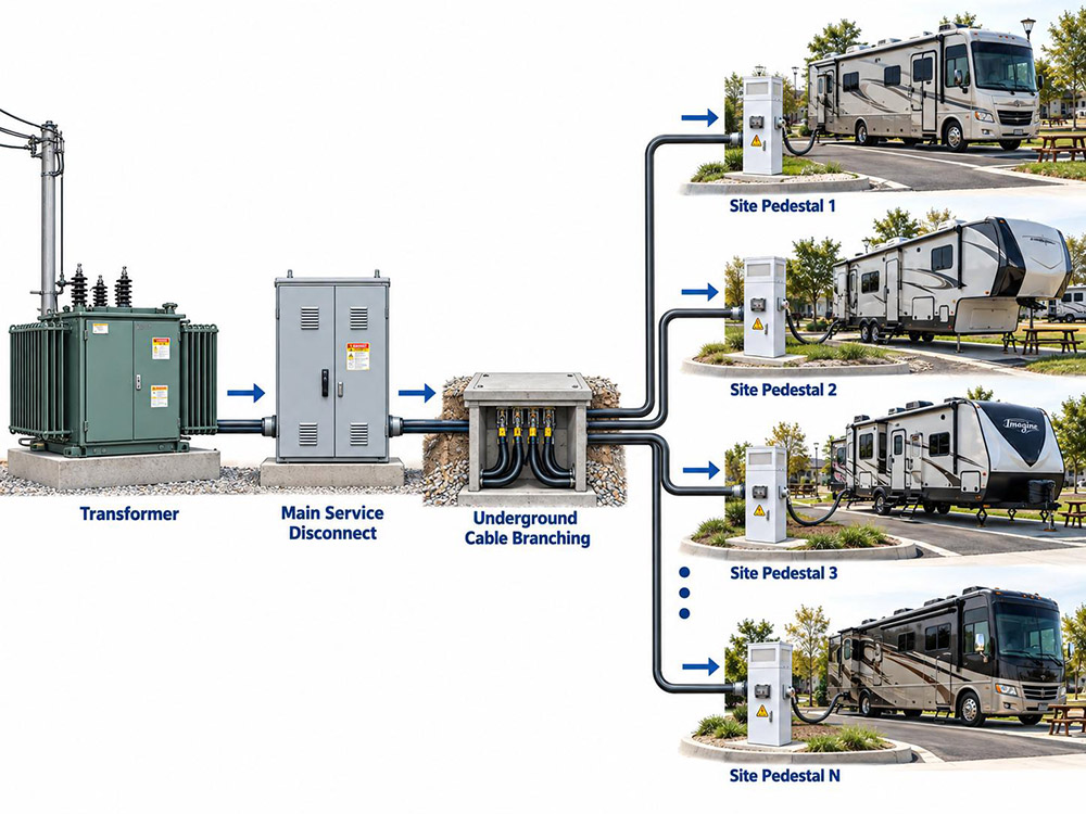
A large RV park is an electrical system with a transformer at its head, and everything downstream, from the main service disconnect to the pedestal at each site, depends on that one upstream asset. Its capacity sets how many sites the park can power and how much growth it can absorb later.
Sizing that transformer is a question about the park’s peak demand, not about the number of pedestals alone. Copying one current value across every site oversizes some parks and undersizes others. From the load values and demand factors in the National Electrical Code (NEC), the disciplined path runs through the site load list, the non-site loads, and the service voltage choice.
Key Takeaways
- Transformer sizing starts from a site-by-site load list, not from one value copied across every pedestal.
- NEC Article 551 supplies both the site load values and the demand factors that reduce the total.
- A park with 36 or more sites applies a 41 percent demand factor, which is where large parks usually sit.
- Every powered site needs at least one 20 A / 125 V receptacle, and 125 V 15 A and 20 A receptacles must have ground-fault circuit-interrupter (GFCI) protection.
- Single-phase 120/240 V and three-phase 208Y/120 V services fit different park sizes, site mixes, and the offerings of the local power company.
- The capacity application belongs early in the project, because the power company’s study time and upgrade costs ride on the transformer choice.
What Transformer Sizing Decides
On the supply side of the meter, the transformer serves the whole park through the main service. Its rating in kilovolt-amperes (kVA) caps the current the park can draw at once. That cap reaches back into customer-side design choices: the service entrance conductors, the main switchboard, and the voltage at the last pedestal on a long feeder.
A wrong number causes trouble in both directions. Under summer load an undersized transformer sags, then trips on the hottest afternoon of the season, and it leaves no capacity for sites the owner adds later. An oversized unit raises the capacity charge and the equipment lead time for capacity the park never uses.
Conductors, panels, and feeders that carry power from the service to each site are covered in the guide to RV park electrical service sizing. This article stays on the transformer itself and the interface with the power company.
Starting With the Site Load List
Before any demand factor applies, list every powered site and its largest receptacle. Article 551.71 sets the floor for the site mix. Each site with power gets at least one 20 A / 125 V receptacle. At least 20 percent of the sites get a 50 A / 125/250 V receptacle, and at least 70 percent get a 30 A / 125 V receptacle. GFCI protection is mandatory on the 125 V 15 A and 20 A receptacles, while the 30 A and 50 A supply receptacles carry no such requirement.
Site Load Values in Article 551.73
Article 551.73 assigns a calculated load to each site type. Example values from the earlier edition of the article appear in the table below. Confirm which number your adopted code uses before you commit to a total, because a later edition raised the 50 A site value to 12,000 VA.
| Site Type | Earlier Example Value | Later-Edition Value |
|---|---|---|
| 50 A / 125/250 V site | 9,600 VA | 12,000 VA |
| 30 A / 125 V site | 3,600 VA | 3,600 VA |
| 20 A / 125 V site | 2,400 VA | 2,400 VA |
| Dedicated tent site with 20 A | 600 VA | 600 VA |
These are example values, not one mandatory figure, and the edition adopted in your area controls the number you use. A single-outlet tent site carries a far smaller load than a full RV site.
Why the Site Mix Drives the Total
Multiply the count in each group by its site value, then add the groups. Two parks with the same site count can differ by a wide margin once the receptacle mix changes, since this sum is the connected site load before any demand factor.
Applying the Demand Factor Table
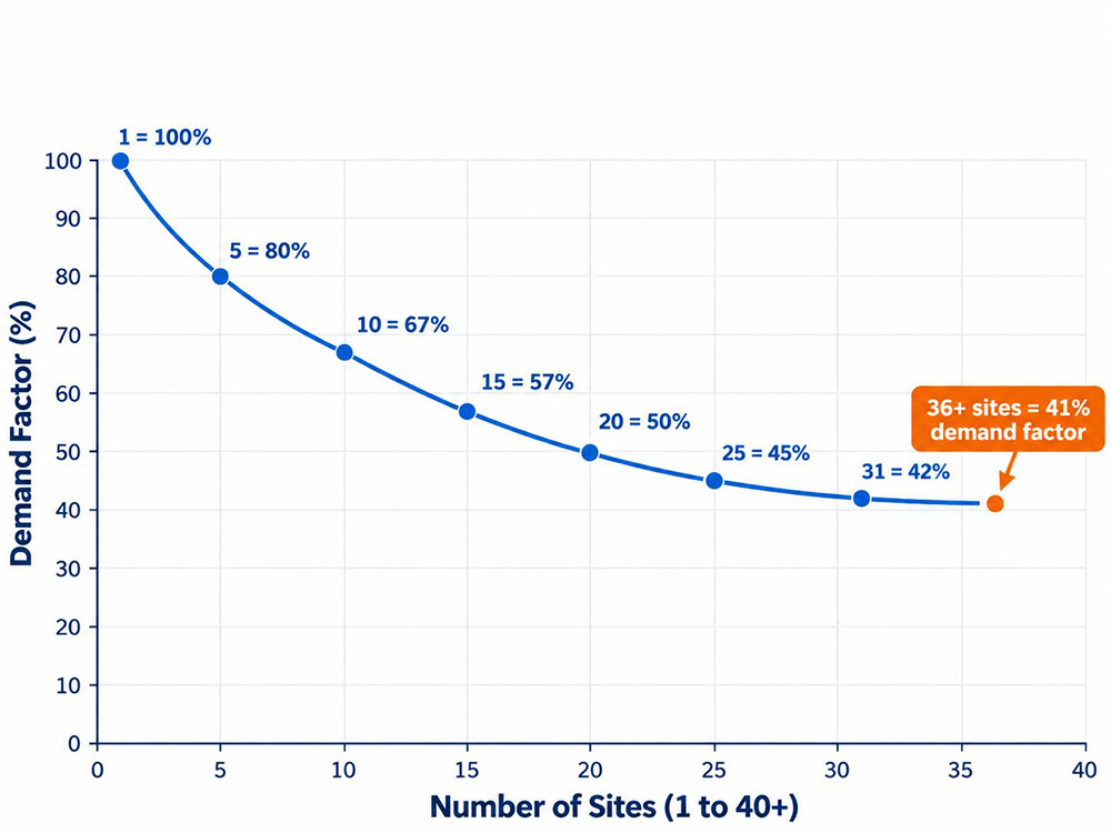
Sites do not all draw their full load at the same hour. One RVer runs the air conditioner at noon, and a neighbor runs it at 4 in the afternoon. NEC Table 551.73 recognizes this diversity and gives a demand factor that falls as the site count rises.
| Number of Sites | Demand Factor |
|---|---|
| 1 | 100% |
| 2 | 90% |
| 3 | 80% |
| 4 | 75% |
| 5 | 65% |
| 6 | 60% |
| 7 to 9 | 55% |
| 10 to 12 | 50% |
| 13 to 15 | 48% |
| 16 to 18 | 47% |
| 19 to 21 | 45% |
| 22 to 24 | 43% |
| 25 to 35 | 42% |
| 36 and above | 41% |
Multiply the connected site load by the factor for the park site count. A park with 40 sites lands in the last row, so its connected site load is reduced to 41 percent.
Adding the Non-Site Loads
Beyond the sites, a park runs its own loads. An office and check-in building, restrooms and showers, a laundry, well or booster pumps, site lighting, and any EV charging or marina service all draw power too. None fall under the site demand factor, so their calculated load is added on top of the site demand load. Size each one from its own nameplate data, lighting schedule, and motor ratings.
Keep the continuous loads separate from the intermittent site load when building the total, because folding everything into one figure loses the detail the power company needs to review.
Choosing the Service Voltage and Phase
Single-Phase 120/240 V Service
Single-phase 120/240 V is the common RV service. It delivers 120 V line to neutral for lighting and small appliances and 240 V line to line for larger loads. That matches how a 50 A RV connects through a NEMA 14-50 configuration under ANSI/NEMA WD 6. For small and mid-size parks, a single-phase service is often the simplest match to the supply line.
Three-Phase 208Y/120 V Service
A three-phase 208Y/120 V service gives 208 V line to line and 120 V line to neutral. It moves more power through smaller conductors and holds voltage better at the end of a long feeder, which suits a large park with dispersed pedestals and heavy common loads. Line-to-line voltage is the tradeoff: a 50 A connection rated 125/250 V sees 208 V instead of 240 V on a 208Y/120 system, and any 240 V equipment runs at lower voltage. Whether that matters depends on the equipment mix, the adopted code, and the power company’s offering, so the choice belongs to the project engineer.
Matching the Connection to the Loads
Article 551.81 ties the site receptacles to ANSI/NEMA WD 6 configurations, including the 14-50, the TT, and the 5-20. Those configurations must arrive at the right voltage from the selected service. Each 50 A receptacle also needs its own branch circuit under Article 551.72, rated to match the receptacle.
Turning Demand Into Transformer Capacity
In volt-amperes, the demand load is what the service must supply. For a single-phase service, current equals the load divided by 240 V. For a three-phase service, current equals the load divided by the square root of 3 times 208 V.
- Total the site demand load after the demand factor.
- Add the non-site loads.
- Convert the volt-ampere total to kilovolt-amperes.
- Compare that value with the transformer sizes the local power company offers.
- Select the next standard size at or above the calculated demand.
- Confirm the selection with the power company’s own study.
Utilities usually own and size the transformer from the load data the park submits, so the figures drive the result. An accurate demand value, plus agreement on the service voltage, phase, and point of connection, keeps the power company’s review short.
A Worked Example for a 40-Site Park
Park A has 40 sites that meet the Article 551.71 mix. Eight sites are 50 A sites, 28 are 30 A sites, and 4 are 20 A sites. At the code minimums, the 30 A group is 70 percent of the park and the 50 A group is 20 percent.
| Site Group | Count | Value Per Site | Connected Load |
|---|---|---|---|
| 50 A | 8 | 9,600 VA | 76,800 VA |
| 30 A | 28 | 3,600 VA | 100,800 VA |
| 20 A | 4 | 2,400 VA | 9,600 VA |
| Total | 40 | 187,200 VA |
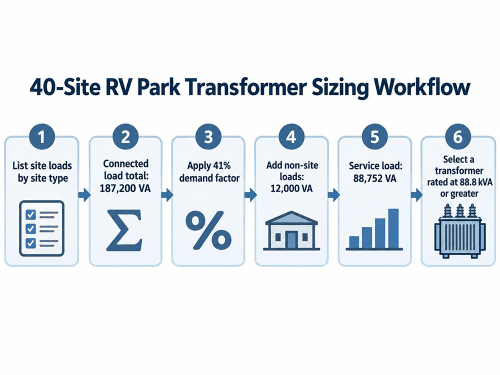
- Connected site load: 187,200 VA.
- With 40 sites, the park takes a 41 percent demand factor.
- Multiplying 187,200 VA by 0.41 gives 76,752 VA at the site level.
- For this example, assume the office, restroom, and site lighting add 12,000 VA. The service load becomes 76,752 VA plus 12,000 VA, or 88,752 VA.
- Divide by 1,000 to get about 88.8 kVA.
- Compare against the transformer sizes the power company stocks and pick the next standard size at or above 88.8 kVA, then confirm with the power company’s study.
If the Adopted Edition Uses 12,000 VA
One 50 A value for every site would bear no relationship to this park’s real mix. With 12,000 VA for each 50 A site, the 50 A group becomes 96,000 VA, the connected load rises to 206,400 VA, and the site demand load becomes 84,624 VA. Confirm the value in your adopted edition before you publish a transformer request.
Dealing With the Power Company on Capacity and Growth
The Capacity Application
Capacity applications start with a load letter and a site plan, submitted by developers, showing the site counts by type, the calculated demand, the desired service voltage and phase, and the point of connection. From there the power company runs its own study, sets the transformer size and service configuration, and quotes any extension or upgrade cost.
Who Owns What
In most arrangements the power company owns and maintains the transformer, while the park owns everything past the service point, including the main service equipment. That line decides who pays to enlarge the transformer when the park grows, so confirm the terms in writing before you commit to a site count.
Planning Room to Grow
Future sites are cheaper to add when the service is built for them from the start. A designer reserves transformer capacity, conduit, and switchboard space for the next phase and documents the demand headroom in the submission to the power company. Enlarging a service later costs more than sizing the first one with room to spare, so pair the reserved capacity with expansion-ready RV power pedestal hardware.
Common Sizing Mistakes
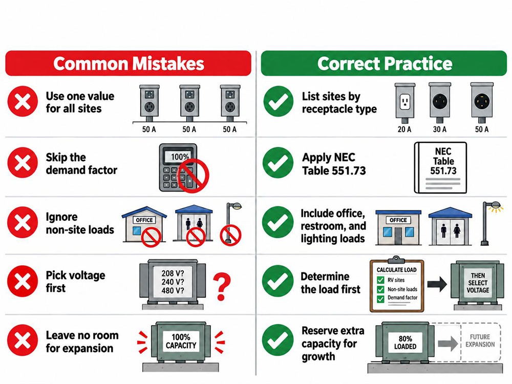
| Mistake | What It Costs | Better Approach |
|---|---|---|
| One current value for every site | Oversizes some parks, undersizes others | Build a site list by receptacle type |
| Skipping the demand factor | Inflates the transformer size | Apply Table 551.73 by site count |
| Ignoring non-site loads | Undersizes the service | Add office, restroom, lighting, and pumps |
| Choosing voltage first | Wrong phase or transformer class | Fix the load, then the voltage |
| No room for expansion | A new service when sites are added | Reserve capacity and space up front |
Frequently Asked Questions
How do I know what size transformer an RV park needs?
Add the site loads by type, apply the Table 551.73 demand factor for the site count, add the non-site loads, and convert the total to kVA. The power company then selects the transformer from that demand figure.
Is a 50 A site always 9,600 VA?
The earlier edition of Article 551.73 used 9,600 VA as the example value for a 50 A site. A later edition raised it to 12,000 VA, so use the value from the edition your jurisdiction has adopted.
Can an RV park use a three-phase 208Y/120 V service?
Yes, and it can suit a large park with dispersed pedestals. A 50 A connection rated 125/250 V sees 208 V line to line instead of 240 V on that system. Confirm the choice against the park equipment and the power company’s offering.
Does every site need a 50 A receptacle?
No: Article 551.71 requires at least 20 percent of sites to have a 50 A / 125/250 V receptacle and at least 70 percent to have a 30 A / 125 V receptacle. Every powered site still needs at least one 20 A / 125 V receptacle.
Who pays to enlarge the transformer?
That depends on where the ownership line falls between the park and the power company. Most arrangements place the transformer on the power company’s side, so the power company carries the replacement cost while the park pays any extension or contribution charge it negotiates.
Sized from a real load list, a transformer protects the park in both directions. It keeps the summer peak from tripping the service, and it keeps the owner from paying for capacity that sits idle. Site lists and the pedestal specifications behind them can be reviewed against the load data to match the right pedestal hardware. Reach out through the contact page to start the conversation.

About the Author
Boda Pan
Engineer, JIYA Intelligent
Boda Pan is an engineer at JIYA Intelligent with five years of experience in outdoor power distribution. He specializes in RV power pedestals, water and power pedestals and marina water and electric pedestals, with a focus on IEC standards compliance.