
Installing a 200-amp pedestal for the RV is always the decision made to guarantee a strong and safe power supply for the RV. Regardless of the installation setting, whether a residential property or a campground, wiring and electrical considerations must be met to fulfill the RV’s power needs and secure the equipment, this guide aims to get rid of any doubt concerning the installation by providing step-by-step instructions to get the job done right, fast, and safely. From covering key points to meeting electrical code requirements, we’ve got everything that makes it easy, stress-free, and even enjoyable. Read on to learn how this RV pedestal setup gets your power running in no time!
Understanding RV Pedestals

An RV pedestal acts as a dedicated power supply for supplying power to recreational vehicles. Such a pedestal typically provides standard electrical hookups, including 30-amp and 50-amp outlets, to accommodate the varying power needs of RVs. They are installed in campgrounds, parks, and some private properties to allow an RV owner to plug in power directly to their vehicle. It provides RVs with a fair and safe power supply for operating appliances, charging batteries, and maintaining general comfort while on the road. Proper installation and maintenance of the RV pedestals become critical for their consistent performance and safety.
What is an RV Pedestal?
An RV pedestal is a utility box designed to provide electrical hookups for recreational vehicles. These pedestals offer multiple outlets, commonly with 120V and 240V connections, including 20A, 30A, and 50A, to address the various power requirements of RVs. Most modern RV pedestals are also equipped with circuit breakers and surge protection and can include water and cable TV hookups, depending on the location. They are typically used at campgrounds, RV parks, and residential homes to provide power to RV owners, allowing them to operate appliances, lighting, air conditioning systems, and other essential systems. For the sake of convenience and safety, RV pedestals are designed to withstand all sorts of outdoor conditions and meet industry standards.
Types of RV Pedestals
Pedestals can be metered, unmetered, lighted, stainless steel, or pad-mounted types for motorhomes.
| Type | Features | Material | Mounting | Usage | Safety |
|---|---|---|---|---|---|
| Metered | Tracks usage | Steel | Surface | Billing | Circuit Prot. |
| Unmetered | Basic power | Steel | Surface | General | Circuit Prot. |
| Lighted | Illumination | Steel | Surface | Night Use | Circuit Prot. |
| Stainless Steel | Corrosion Res. | Stainless | Surface | Durable | Circuit Prot. |
| Pad-Mounted | Fixed setup | Steel | Pad | Permanent | Circuit Prot. |
Importance of Proper Installation
Due to safety, functionality, and durability concerns, proper installation of the pedestal is essential. In the event of improper installation of the pedestal, dangers such as electrical hazards may develop, causing damage to the equipment or other incidents, including fires. According to the National Fire Protection Association (NFPA), faulty electrical systems are among the leading causes of fires in RVs and camping setups. The installation of RV pedestals in compliance with NFPA 70 (National Electrical Code) effectively reduces these risks.
Key factors to observe during installation include verifying proper wiring, ensuring the correct construction of circuit breakers, and ensuring appropriate grounding. A substandard grounding would allow for electrical surges, which cause damage to approximately $1 billion worth of home and RV electrical equipment annually in the United States. Additionally, weather-proofing of materials and components during the installation operation will enable the pedestal to withstand environmental factors that could otherwise cause it to fail. Such include rain, snow, and UV rays, which all would have shortened its operational life.
Initially, it would be wise to hire an electrician or certified technician to install or at least inspect the pedestal. They shall do that while ensuring compliance with local electrical codes, which lessens the future chance of failure. Further periodic inspection, checks, and testing shall guarantee efficiency in terms of safety, contributing to maximum convenience for the owner and reliability in power sourcing for the RV.
Preparing for Installation
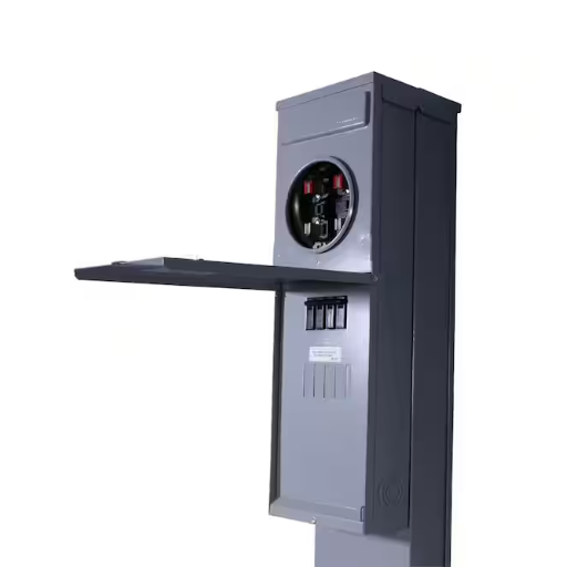
In preparation for the installation of an RV power pedestal, one should first choose a site that allows easy access for RVs and complies with local regulations. The site should be level, firm, and unobstructed. One should verify that the power supply matches the pedestals’ needs, such as a 30- or 50-amp service. Next, you’ll want to prepare all your basic supplies and tools, and in some cases, you may need to include wiring and weatherproof enclosures. Safety must be given consideration; therefore, turn off the power supply at this point. Also, note that local building codes and permit requirements should be checked during the installation procedure, and it may be necessary to have the setup done by a licensed professional to ensure compliance with the installation.
Tools and Materials Needed
The following tools and materials are very much required to complete the installation of the pedestal:
- Screwdriver Set – For tightening connection screws during assembly.
- Wire Strippers and Wire Cutters – To strip wire ends and to cut wires to suitable lengths.
- Voltage Tester – To check if power is off before commencing work.
- Conduit and Fittings – To channel and protect the cables.
- Weatherproof Enclosure – To protect connections from outdoor elements.
- Wire of Proper Gauge – Concerning the amperage rating of either 30-amp or 50-amp.
- Circuit Breakers – Suitable for the electrical requirements.
- Drill and Anchors – To hold the pedestal firmly in place.
- Electrical Tape – To mask wire connections.
Organizing these materials according to the specific work at hand will allow you to save time and maintain clarity and safety during manual application, adhering to standards.
Understanding Your RV Power Requirements
First and foremost, it is essential to understand the exact power requirements of your vehicle to ensure a smooth connection to the electrical system. The majority of RVs are equipped with either 30- or 50-amp systems, which simply refer to the amount of electricity available for powering your devices and appliances. Working under these general assumptions, you would say that a 30 amp system provides 3,600 watts (120 volts times 30 amps), and a 50 amp system will provide up to 12,000 watts if it utilizes both legs of the 120 volts. The easiest way to determine what your RV requires is to refer to the owner’s manual or simply inspect the power connection inlet on your RV. Knowing this can help you with avoiding circuit”, “FINE”, “delicate, which is to help you avoid overloading circuits and can help align your electrical requirements with those of campground or pedestal setups.
Choosing the Right Location
Several factors should be considered when selecting the perfect location for your RV vacation. Start by deciding on what kind of setting you want — hanging out on a quiet mountainside, on a sunny beach, or in a wooded campground. The site must be accessible, ensuring your RV can arrive and park without any issues. Determine if your needs for amenities such as water hookup, electricity, Wi-Fi, or waste disposal are met at the site. You may also want to consider the distance to local attractions, hiking trails, or other areas where leisure activities take place. A valuable tool in your arsenal is Google Maps, along with various campground directories that provide further insight through reviews and photos posted by fellow travelers.
Wiring an RV Pedestal
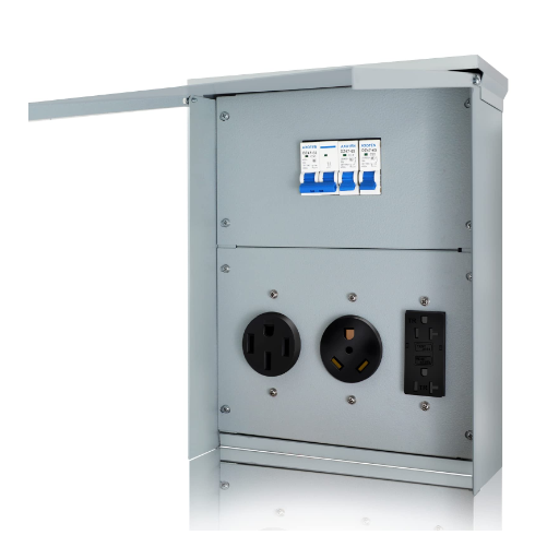
An RV pedestal must be wired appropriately to provide a safe and reliable power supply to the RV. Use the following instructions:
Turn Off Power – Before beginning, switch off the power supply to the pedestal to eliminate any risk of electrical hazards. A voltage tester must be used for confirmation.
Identify the Connections – Pay attention to the pedestal wiring terminals. Usually, they are:
Hot (Black or Red Wire) – This carries the electrical current.
Neutral (White Wire) – Completes the circuit by returning the current.
Ground (Green or Bare Wire) – Prevents electric shock.
Connect the Wires – The wires should be wound around the terminals, and the terminals should be tightened. Connect:
The hot wire to the terminal is labeled “Hot” or “L.”
Connect the neutral wire to the terminal marked “Neutral” or “N.”
Ground wire to the terminal marked “Ground” or “G.”
Tighten and Inspect – Tighten every connection to ensure the wiring is secure, as loose connections can cause overheating and faults. Inspect every wiring to ensure it is attached to the correct terminal.
Restore Power and Test – After completing the wiring, power must be restored to the pedestal. Using a voltmeter, test the outlet to ensure it is supplying the correct voltage (typically 120V or 240V, depending on your RV requirements).
If you are unsure about anything, for safety, hire a qualified electrician or professional to do the job. Adhere to all local electrical codes and standards.
Basic Wiring Principles
When handling electrical wiring, some safety and operational rules should be followed. Highly important is ensuring that the power is switched off from the source before doing any electrical work. Insulated tools should be used whenever possible to reduce shock hazards. Wires must be handled with care, avoiding contact with exposed parts. Usually, the colors help them to be identified: black or red is hot, white is neutral, and green or bare is ground. Connections should be securely fastened, using terminal screws or wire nuts as required, to prevent any loose or defective wires. Finally, use the multimeter again to verify that everything is connected correctly and has the correct voltage levels; this will ensure the system is functioning properly.
Connecting to the Main Panel
Feeding the main panel must be done only with a thorough understanding of electrical systems and strict adherence to stringent safety precautions. First, switch off the main breaker to cut the power supply. Route the wires carefully through a suitable conduit for neatness and protection. Connect the circuit wires in the panel to their respective terminals-hot wires to breakers, neutral wires to neutral bus bar, and ground wires to ground bus bar. Check all connections again to be sure that all are tight and secure. Use the circuit tester or multimeter to verify the wiring against any errors before switching the power back on. When in doubt, always have a licensed electrician handle this for you to ensure safety and compliance with local codes.
Installing a Meter for Monitoring
Installing energy meters is often considered one of the most practical ways to provide valuable information on electrical consumption and to determine efficiency, thereby reducing operational costs. First, identify a sound meter that suits the requirements of your system. As a safety measure, turn off the power supply and mount the meter close to the main electrical panel. Continue wiring your meter according to the manufacturer’s directions. Ensure line, load, neutral, and ground connections are appropriately connected. After installation, restore the power supply and test the meter. Smart meters are beneficial because they provide granular real-time data that can further be accessed through their mobile apps or Web interfaces to make energy tracking and management as efficient as possible.
Testing and Safety Checks
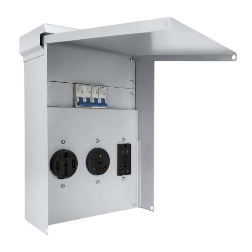
Depending on the type of smart meter being installed, standard tests for proper operation may include:
- Display Check – To confirm that the energy (electrical consumption) data is being transmitted through the meter and displayed correctly on the display or the pair-down app.
- Power Consumption Readings – Compare the instant reading with past consumption data or a trusted meter for accuracy.
- Stable Power Supply – Ensure the installation causes no fluctuations or interruptions.
- Connections – Ensure all wiring connections are securely insulated.
- Keep Watch for Alerts – Monitor the meter for any faults or alerts that may indicate an issue.
If anything unusual is spotted, refer to the guide for the meter or contact a professional electrician to remedy the problem safely. Always observe safety procedures, including using tools and wearing protective equipment, when inspecting the meter.
Verifying Connections
Connections are tested for correct electrical functioning. Start by visually inspecting whether the wires are connected to the proper terminal as per the wiring diagram. Loose or unsecured wires can cause inaccurate readings or operational hazards. Using a multimeter to check continuity or voltage points follows the following process. If all readings are as expected and power is flowing, the connections are fine. In the event of erratic meter behavior or a result indicating a possible fault, refer to the device manual for troubleshooting or contact an electrician. Maintaining an efficient connection is key to the meter’s accuracy and the system’s reliability.
Testing for Proper Functionality
To test if the device is working correctly, first check the nurse’s physical condition, the condition of their connections, to see if there is any wear and tear, damage to a wire, or loose wiring. If the device has one, then do the calibration test using the manufacturer’s instructions to align the readings. Most modern testing equipment has a diagnostic mode that quickly identifies common faults. Additionally, compare your findings to the standard operating parameters described in the user manual or technical documentation. Hands-on testing, combined with independent information from updated manufacturer FAQs or reliable online resources, should present a detailed view of the problem. Always observe strict safety measures when working on any electrical system, and if you have any doubts, consider seeking the assistance of a professional for further diagnostics.
Safety Tips for RV Power Installation
- Turn Off Power Sources
Before carrying out any power installation, always turn off the power to protect against the risk of electric shock injuries. This means the RV should be disconnected from shore power, and if a generator is installed, it should be switched off.
- Use Suitable Tools and Equipment
Always use tools and equipment meant for electrical work. Insulated tools, voltage testers, and circuit analyzers are some valuable ones that will guarantee installation accuracy and safety.
- Ground What Should Be Grounded
Verify that the RV electrical system is grounded in a manner that prevents electrical surges and shocks. Improper grounding could also lead to a life-threatening hazard.
- Check All Cables and Connections
Inspect thoroughly for any signs of wear, fraying, or damage in all electrical cables, wires, and connections. Any found up to such a standard must be considered for replacement before installation.
- Follow Local Codes and Regulations
Follow local electrical codes and regulations to ensure that safety standards are upheld for the installation. This could include verifying if there are any requirements for breaker amp ratings, wire gauge sizes, or even connection types.
Reference Sources
-
VANPEURSEM ARCHITECTS PROJECT NUMBER 23395
This document describes RV connection pedestals mounted on precast concrete posts, along with their electrical arrangements.
View Source -
PROJECT MANUAL
Detailed instructions for setting up electrical distribution panels, including RV pedestals.
View Source -
Lake of the Ozarks State Park, Kaiser, Missouri
Project drawings for the installation of RV power pedestals on concrete pads at the campsites.
View Source
Frequently Asked Questions (FAQs)
How to Install an RV Pedestal: What Tools Are Needed?
To install an RV pedestal, you will need several essential tools, including a shovel for digging a trench, a wire stripper for preparing the conductors, a screwdriver for securing the receptacle, and a level to ensure proper alignment. Additionally, you’ll need a grounding rod, lugs for connecting wires, and an amp breaker suitable for your required amperage, such as a 50-amp or 30-amp outlet, depending on your RV’s needs.
What Are the Steps to Install an RV Power Pedestal?
The steps to install an RV power pedestal include selecting a suitable location, digging a trench for the direct burial of the feeder wires, installing the pedestal according to the manufacturer’s instructions, and connecting the wires to the receptacle and breaker. Ensure that the pedestal is properly grounded with a grounding electrode and that all connections are secure to prevent voltage drop.
Do I Need to Hire a Professional to Install an RV Pedestal?
While it is possible to install an RV pedestal yourself if you have electrical knowledge and skills, hiring a professional electrician is recommended for safety and compliance with NEC standards. A qualified electrician can ensure that the installation complies with local codes, especially when dealing with high voltages, such as 240 volts or 200 amps.
What Is the Proper Voltage for RV Pedestal Installation?
Most RV pedestals are designed to accommodate different voltage requirements, typically featuring 30-amp or 50-amp outlets operating at 120 volts. However, for larger RVs, a 200 amp meter may be necessary to provide adequate power. Always check the voltage requirements of your RV and ensure that the installation adheres to local electrical codes.
How Deep Should I Bury the Feeder Wires for My RV Pedestal?
Feeder wires for an RV pedestal should be buried at least 24 inches deep if using direct burial wire, as specified by the NEC. This depth helps protect the cables from physical damage and environmental factors. It is essential to verify local codes, as some areas might have specific requirements regarding burial depths.
What Type of Grounding Electrode Should I Use for RV Pedestal Installation?
A grounding electrode, such as a ground rod, is essential for RV pedestal installation to ensure safety. The NEC requires a grounding rod to be driven into the ground, providing a path for electrical faults. The grounding system must be appropriately connected to the RV panel to help minimize the risk of electrical shock.
Can I Use an Adapter for Different Amp Ratings When Installing an RV Pedestal?
Yes, you can use an adapter to connect your RV to a different amp rating pedestal, such as using a 30 amp hookup with a 50 amp RV. However, ensure that the adapter is rated for the appropriate voltage and amperage to prevent overheating and potential electrical hazards. It’s advisable to use adapters that comply with NEC guidelines.
What Is the Demand Factor for RV Pedestal Circuits?
The demand factor refers to the maximum load that is expected to be used on the circuit at any given time. For RV installations, especially those with multiple circuits or when planning for high-demand appliances, it’s crucial to calculate the demand factor correctly to ensure that the installed pedestal can handle the load without tripping breakers or causing voltage drop issues.
Tags

About the Author
David Richardson
Senior Technical Writer, Jiya
David has over 12 years of experience in marina systems and industrial equipment. He works closely with engineers and project teams to translate complex technical topics into practical guidance for operators, installers, and procurement professionals worldwide.