
A power pedestal does more than deliver electricity to an RV or a boat. It also carries the safety path that sends fault current back to the source, so a breaker trips instead of a person getting shocked. That path is the grounding system, and inspectors treat it as the most important part of the installation.
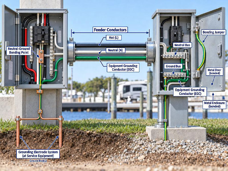
This guide explains what grounding must accomplish on a pedestal, how the equipment grounding conductor does its job, and where marina rules differ from RV park rules. It draws on Article 555 for marinas, Article 250 for grounding and bonding, and Article 551 for RV sites. JIYA builds power pedestals so a qualified electrician can land a compliant grounding system on site. Grounding is not one wire and not one rod, but a system of conductors, bonds, and connections that must all hold together.
Key Takeaways
- The equipment grounding conductor (EGC) provides the low impedance path that lets an overcurrent device clear a ground fault.
- NEC 555.37 requires the marina EGC to be an insulated conductor, sized per 250.122 and never smaller than 12 AWG.
- Neutral and ground are bonded only at the service, then kept separate everywhere downstream, including at the pedestal.
- Metal enclosures, doors, and wiring devices must be bonded so no metal part can become energized.
- The grounding electrode system handles lightning and surges, while the EGC handles fault current.
- A missing or loose bonding jumper is one of the most common defects found during marina inspections.
- Every grounding design must be checked against the locally adopted code edition and confirmed with the authority having jurisdiction (AHJ).
What Grounding on a Power Pedestal Must Accomplish
Grounding does two separate jobs on a pedestal, and mixing them up is where most errors begin. First comes a reliable path for fault current. If a live conductor touches a metal part, that current has to flow back to the source in enough volume to open the overcurrent device. Second, the voltage of metal parts must stay near the voltage of the earth, which limits shock risk.
Only one conductor is built for the first job, and that is the equipment grounding conductor, which must run with every circuit that leaves the service. A pedestal without a continuous EGC may power a load well and still fail the moment a fault occurs, because the current has nowhere safe to go.
This is also why a pedestal needs more than a ground rod, since the earth is a poor conductor over short distances. Fault current needs a metal path back to the source, not a path through the soil. Below, the table separates the parts of the system and the job each one performs.
| Component | Job it performs | Where it belongs |
|---|---|---|
| Equipment grounding conductor (EGC) | Carries fault current back to the source to open the overcurrent device | Runs with every feeder and branch circuit |
| Main bonding jumper | Connects the neutral and the ground at one point | Service equipment only |
| Grounding electrode system | Dissipates lightning and surge energy into the earth | At the service and where the code requires it |
| Bonding jumper | Ties metal enclosures, doors, and devices together | Any metal part that could become energized |
| Neutral conductor | Carries normal return current under load | Every circuit, kept separate from ground downstream |
The Equipment Grounding Conductor and the Return Current Path
As the backbone of fault protection, the equipment grounding conductor depends entirely on continuity. It starts at the service, travels with the feeder, and ends at every enclosure and device it protects. Any break along that run turns the whole safety path into a dead end.
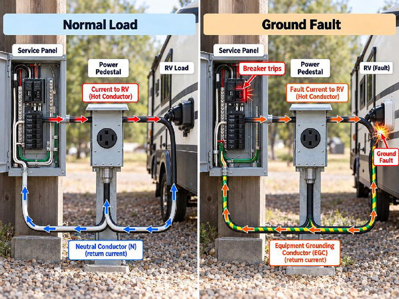
Every circuit has a return path, and the two paths behave differently. Under normal load, current returns through the neutral conductor, and under a fault it returns through the equipment grounding conductor. Any steady current on the EGC during normal operation signals a problem, because that conductor is not meant to carry load current.
Engineered as the lowest impedance route back to the source, the EGC carries a large fault current that trips the breaker. A high impedance path delays that trip, so metal parts stay energized longer, which is exactly what causes shocks and fires. Continuity also means tight terminations and correct lugs, which is why inspectors check it before the cover goes back on.
The Marina Rule for Insulated Equipment Grounding Conductors
Marinas follow a stricter grounding rule than dry land sites, because the environment is wet, corrosive, and full of people near water. Under NEC 555.37, the equipment grounding conductor at a marina must be an insulated conductor. It must also be sized per 250.122 and never smaller than 12 AWG. Insulation is not decoration here, because moisture, salt, and airborne corrosion attack exposed copper, and a bare ground conductor can deteriorate faster than the rest of the run. An insulated EGC stays protected along its length and keeps the ground path independent of the raceway and its couplings.
A 12 AWG floor works with the sizing rule in 250.122. That article sizes the EGC according to the rating of the overcurrent device ahead of it, and 555.37 adds a minimum so the conductor never drops below a practical size. Final size depends on the circuit, so the installer matches the conductor to the overcurrent device, and when in doubt the adopted code edition and the AHJ settle the detail. Fault current at a marina can travel through water as well as metal, and our notes on ground fault protection in marinas explain how that layer works alongside grounding. A correct EGC and a working ground fault device are partners, not substitutes.
Bonding Metal Enclosures and the Pedestal Body
Bonding ties metal parts together so they stay at the same voltage. Every pedestal is full of metal: the enclosure, the hinged door, the mounting bracket, the device yokes, and often the post itself. If a live conductor contacts any of them, that part must connect to the EGC so the fault current has a route home.
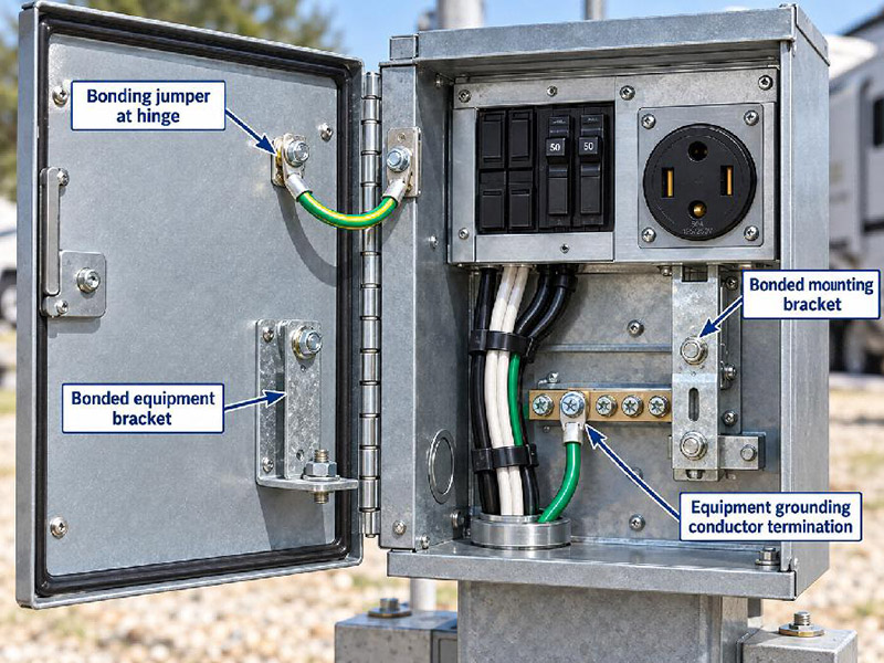
Doors create a specific challenge, because a hinged door is a moving part, and paint, gaskets, and worn hinges can break the electrical connection to the box. Across the hinge, a bonding jumper solves this, and it is a small part inspectors look for on every enclosure. Metal-to-metal contact alone is not proof of a bond, because corrosion and coatings interfere over time.
Bond the pedestal body the same way, since any pedestal mounted on a metal post or structure must be bonded so the whole unit shares one voltage reference. On a marina dock, the surrounding structure may also be metal. Our power pedestal range is designed with clear grounding and bonding points for field wiring.
The Grounding Electrode System and Neutral Separation
Connecting the electrical system to the earth, the grounding electrode system handles a threat the EGC was never meant to address. Lightning, grid switching, and surges arrive as temporary overvoltage, and the electrode system gives that energy a route to the ground. It also stabilizes the system voltage reference under normal conditions.
Grounding electrodes come as a rod, a plate, a concrete-encased electrode, or a combination set by the code. Exact requirements live in Article 250 and depend on the installation and the soil. Treating a ground rod as a substitute for the EGC is a classic mistake, because the earth will not carry enough current over a short path to trip a breaker. In dock work, NFPA 780 for lightning protection and NFPA 303 for marina and boatyard fire safety can guide the wider design.
Neutral and ground must be bonded at one point only: the service. Everywhere downstream, including inside the pedestal, they stay separate. This rule keeps normal return current off metal parts and removes a shock hazard that would exist even with no fault present. Inside a pedestal, the neutral stays on the neutral bus and the ground stays on the ground bus, and there is no main bonding jumper because the pedestal is not the service.
Common Grounding Mistakes and How to Correct Them
Most grounding failures come from a short list of recurring errors that an electrician can catch during a walkthrough but is easy to miss once covers are back in place. Below, the usual defects map to their cause and the correction that resolves each one.
| Common mistake | Why it is a problem | Correction |
|---|---|---|
| Using the metal conduit as the only EGC | A loose coupling, corrosion, or a broken connector interrupts the path | Install a dedicated equipment grounding conductor in the raceway |
| Bonding neutral to ground inside the pedestal | Creates parallel neutral paths and puts current on metal parts | Keep the neutral and ground bond at the service only |
| Skipping the EGC at a marina because the run is short | Fault current cannot clear, and the water raises shock risk | Run an insulated EGC sized per 250.122, never smaller than 12 AWG |
| Leaving a bonding jumper off a hinged door | An energized door can shock the next person who touches it | Fit a bonding jumper across the hinge |
| Using an undersized or unlisted conductor | The path cannot carry fault current long enough to open the device | Match the EGC to the overcurrent device and the code minimum |
| Painting over a bonding surface | Insulates a joint that is meant to be conductive | Clean the surface and bond metal to metal |
Each error breaks a connection the design assumes is intact, so the install has to be verified rather than trusted.
A Step-by-Step Grounding Verification Process
A short checklist turns the rules above into field practice, and steps 1 through 7 cover the sequence to follow before a pedestal is energized.
- Confirm the adopted code edition and contact the AHJ with any open question before work begins.
- Trace the equipment grounding conductor from the pedestal back to the service equipment.
- Verify the EGC size against 250.122 and, at a marina, confirm an insulated conductor of at least 12 AWG.
- Check that the neutral and ground are separate inside the pedestal and that no bonding jumper is present.
- Confirm that every metal enclosure, door, and device is bonded, including the pedestal body and mount.
- Inspect terminations, lugs, and torque, and confirm that no joint relies on paint or corrosion-prone contact.
- Document the installation with photos and notes so the inspector can verify the work against the design.
A verification pass catches the loose lug and the missing jumper that a glance would pass over. It also gives the owner a record of a compliant install for insurance and inspection reviews. Procurement teams get faster work from a pedestal with clear grounding and bonding points, and the full range appears on our products page.
Frequently Asked Questions
Does each power pedestal need its own ground rod?
Not always. Normally the grounding electrode system is established at the service, and the pedestal connects to it through the equipment grounding conductor. A rod at every pedestal is not a substitute for a continuous EGC, so confirm the requirement against the adopted code edition and the AHJ.
Can the conduit serve as the equipment grounding conductor?
Some raceway systems are listed for that use, but NEC 555.37 calls for an insulated EGC at marinas, and relying on conduit in wet or corrosive locations is risky. A dedicated insulated conductor keeps the ground path intact.
Why must the EGC be insulated at a marina?
Marina environments are wet and corrosive, with many people near the water. An insulated conductor protects the ground path from salt and moisture that attack bare copper over time, and NEC 555.37 sets a minimum size of 12 AWG so the conductor can carry fault current.
What is the smallest equipment grounding conductor allowed at a marina?
NEC 555.37 requires the EGC to be sized per 250.122 and never smaller than 12 AWG. Final size follows the rating of the overcurrent device that protects the circuit. Check both rules against the code edition your project adopts.
Grounding is invisible when it works and dangerous when it fails, because each rule closes a path that could otherwise carry current toward a person. If your project needs pedestals with clear grounding and bonding provisions, reach out through our contact page and we will work through the details with your electrical engineer and AHJ.

About the Author
Boda Pan
Engineer, JIYA Intelligent
Boda Pan is an engineer at JIYA Intelligent with five years of experience in outdoor power distribution. He specializes in RV power pedestals, water and power pedestals and marina water and electric pedestals, with a focus on IEC standards compliance.