
For campgrounds with twin-vehicle pitches, choosing one dual-sided water and power pedestal instead of two single-sided units affects civil works, cable routing and maintenance across the entire life of the site. The GRWE1002020D-R serves two pitches from one stainless steel column carrying four sockets and two water faucets. This guide covers how the unit is built, how its electrical protection is coordinated, what enclosure ratings it carries, and what installation and maintenance work a project team needs to plan for.
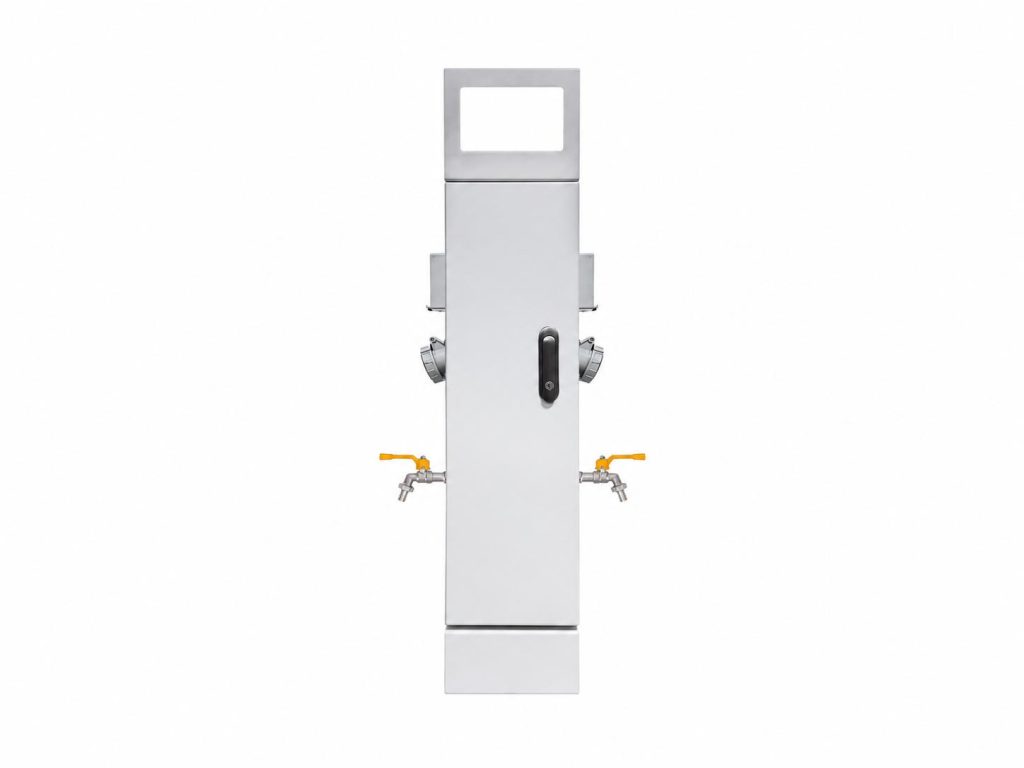
What the GRWE1002020D-R Includes as Standard
The GRWE1002020D-R is a dual-sided water and power pedestal in the GRWE100 series. The three models in this series, and the way they differ from one another, were introduced in an earlier article on GRWE100 series water and power pedestals for RV parks and campgrounds. The D-R variant is the configuration intended for standard twin-vehicle pitches, where two bays sit either side of one service point and both vehicles connect from the same column.
| Specification | Detail |
| Model | GRWE1002020D-R |
| Type | Dual-sided water and power pedestal |
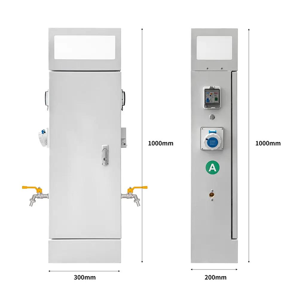
| Dimensions (H × L × W) | 1000 × 200 × 200 mm |
| Sockets | 4 |
| Water faucets | 2 |
| Housing material | Thickened 304 stainless steel, 316 optional |
| Electrical protection | Leakage, overload, short circuit |
| Leakage protection value | ≤30mA / 0.1S |
| Lighting | Integrated LED |
| Control | Independent water and power control |
The unit measures 1000 × 200 × 200 mm and provides four sockets and two water faucets, with leakage, overload and short-circuit protection built in. Power and water are supplied from the same column, so both pitches finish their connection at one point rather than at two separate positions on the site. That single-point arrangement is the main reason the product exists, and the sections below explain what it changes in practice.
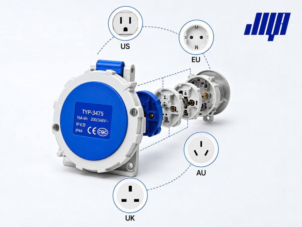
One feature that carries weight in export projects is the modular socket interface. The GRWE100 series uses an interchangeable socket design rated 16A-6h at 200/346V, with IP67 protection on the socket and CE and CQC certification. The interface plate can be supplied to US, EU, AU and UK standards from the same pedestal body. A campground that attracts international guests can therefore specify the socket type its vehicles actually use, without changing anything else about the unit.
How the Dual-Sided Column Is Built Inside
Only by understanding the internal layout can you understand how a dual-sided unit differs from two separate units on site. The differences are not cosmetic, because they determine how the unit behaves when something fails after several seasons of use. They also determine how quickly a technician can reach the fault once it appears.
Housing and Enclosure
The housing of the GRWE1002020D-R is thickened 304 stainless steel, formed as a single piece. A stainless steel housing matters at pitches where vehicles pass close to the pedestal, because the surface has to resist impact and corrosion at the same time. Coated steel and plastic enclosures can look acceptable on delivery and then fail within a few seasons at coastal or high humidity sites. The material choice is therefore a specification decision, not an aesthetic one. A single-piece formed housing also removes the seams where water tends to collect and where corrosion usually starts.
Electrical Compartment
The electrical compartment runs the length of the column and serves both sides. Inside the column are the industrial sockets, the leakage protection device, the overload and short-circuit protection devices, and the terminal blocks that connect the incoming supply to each circuit. Both pitches draw from the same compartment, so the protective devices have to be coordinated against the combined load, not against a single pitch. Installers sometimes miss this when they treat a dual-sided unit as two separate pedestals sharing a housing. The components are arranged so that a technician can reach the terminations through the service door without removing the sockets.
Water Compartment
The water section is physically separated from the electrical compartment, with faucets serving both sides. Placing the two functions in separate compartments keeps moisture away from electrical components, which makes operation safer and reduces the maintenance attention the unit requires. The separation is physical rather than a matter of sealing alone, so a leaking connection on the water side drains and vents away from the electrical side instead of collecting inside the same space.
Separation Panel and Lighting
A separation panel runs the full length of the column to divide the electrical and water sections, and an integrated LED provides illumination for night-time connection. Both details address the same practical problem. Guests arrive and connect after dark far more often than site designers expect. A guest who cannot see the socket is a guest who calls the warden, forces a socket cover, or connects incorrectly. Lighting the connection point reduces all three outcomes.
How the Electrical Protection Chain Works
The electrical design follows a protection chain, in which the protective device, the cable and the socket must be coordinated so that a fault is cleared before any element in the chain is overloaded. A pedestal can carry every protection function listed in a specification and still perform badly if those three elements are not matched. The coordination detail therefore matters more than the component list.
Protection Components and Standards
Every component in the protection chain is selected to a specific standard:
| Component | Standard |
| Miniature circuit breaker (MCB) | EN IEC 60898-1 |
| Residual current circuit breaker (RCCB) | EN IEC 61008-1 |
| RCBO (combined MCB and RCCB) | EN IEC 61009-1 |
| Molded case circuit breaker (MCCB) | EN IEC 60947-2 |
| Industrial sockets | EN IEC 60309-1 / EN IEC 60309-4 |
| Panel sockets | EN IEC 60884-1 |
| Terminal blocks | EN IEC 60947-7-1 |
| Cable | EN IEC 60227-3 |
Breaker, Cable and Socket Coordination
For protection to operate as intended, three ratings must be matched:
- The rating and breaking capacity of the protective device
- The current-carrying capacity of the cable
- The current rating of the socket
The protective device has to operate before the cable reaches its thermal limit, and the socket has to be rated for the load it carries. If the breaker rating is too high relative to the cable, the cable can be overloaded before the device trips, and the pedestal becomes a fire risk that passes every visual inspection. If the breaker rating is too low relative to the load, guests experience nuisance tripping during peak evening demand. The operation then gains a reputation for unreliability that service visits alone will not repair.
Because the correct ratings depend on the load per pitch, the cable run length and the site distribution design, they are confirmed at the project specification stage rather than fixed for all installations. The JIYA team provides this coordination as part of the project review, so the ratings arrive on site already matched to the distribution design instead of being decided by whoever installs the unit. Where the supply arrangement changes after specification, the coordination should be reviewed again rather than assumed to still hold.
Grounding
Grounding provides a defined return path for fault current, allowing the protective device to operate reliably. Two aspects need attention during installation. The first is grounding continuity, where the resistance between the pedestal ground terminal and the site ground electrode is verified at ≤0.1Ω before handover. The second is the grounding arrangement itself. A pedestal connected to a site grounding system that does not suit the local supply configuration will not clear a fault, however well the pedestal itself is built. Installation should follow the applicable local code, and at international level IEC 60364-5-54 covers grounding arrangements and protective conductors.
Insulation Verification
Insulation resistance is verified at handover. The requirement is ≥10MΩ at 500V test voltage, measured between live conductors and ground and between live conductors and the enclosure, with each circuit tested for at least 30 seconds. Recording these readings matters as much as achieving them, because the values provide a baseline that later maintenance visits can be compared against. A circuit that reads 15MΩ at handover and 12MΩ two years later is showing an early trend that a reading of 12MΩ alone would not reveal.
What IP and IK Ratings Apply to the Pedestal
Protection ratings describe what the pedestal enclosure and its components withstand. The ratings below apply to the GRWE100 series. They are stated separately for the enclosure and for the sockets, because the two are exposed to different conditions in service.
| Item | Rating | Meaning |
| Overall enclosure | IP54 | Dust protected; protected against water splash |
| Sockets | IP66 and above | Protected against powerful water jets |
| Impact resistance | IK10 | Resistant to deliberate damage and hard object impact |
IP ratings are defined by IEC 60529, which specifies the degrees of protection provided by enclosures. IK ratings cover resistance to mechanical impact. IP54 on the enclosure means the unit can be installed in the open at a campground without additional shelter. The higher socket rating matters because the socket is the part a guest touches, and the part most exposed to hose water, sideways rain and impact from a hose reel or a vehicle door.
How the Pedestal Handles Salt Spray and Coastal Humidity
Unlike inland sites, coastal and waterfront installations involve airborne salt, sustained high humidity and more frequent condensation cycles. These factors affect both the enclosure and the electrical components inside it. A unit that gives no trouble inland can deteriorate visibly within a few seasons at a marina or a waterfront campground. Three provisions address the problem: material selection, salt spray verification and moisture protection inside the column.
Why 316 Stainless Steel Matters Near the Coast
Material selection is the first decision. 316 stainless steel contains molybdenum, which improves resistance to chloride attack. For projects within a few kilometers of the coast, the material should be discussed with the factory at the specification stage. The cost difference between the two grades is small next to the cost of replacing housings at a working site later.
| Application | Recommended Material | Reason |
| Standard inland sites | 304 stainless steel | Standard series material, suited to normal outdoor exposure |
| Coastal and high salt spray areas | 316 stainless steel (optional) | Better resistance to chloride corrosion |
Salt Spray Testing
The housing of the GRWE100 series is verified by salt spray testing, which reflects the corrosion resistance of the pedestal in marine-influenced environments. The test result applies to the housing material and finish rather than to the complete assembly, so components supplied to a different specification still have to be assessed on their own. For a waterfront project, asking for the salt spray result together with the material grade gives a clearer picture than accepting either one alone.
Moisture Protection Provisions
Moisture protection is the third area. Coastal installation provisions cover the following, and because exposure varies between coastal sites, the specific configuration is confirmed per project. Projects requiring additional protection should raise it during the specification stage.
- Moisture protection provisions within the electrical compartment
- Internal long-term rust prevention treatment
- Physical separation between the water and electrical compartments, so moisture on the water side does not reach electrical components
- UV-resistant treatment for exposed surfaces
When One Dual-Sided Unit Beats Two Single-Sided Units
For campground designers, the practical question is when one dual-sided unit is more suitable than two single-sided units. The comparison below sets out where the two approaches differ, covering both the equipment itself and the site work that surrounds it.
| Factor | One Dual-Sided Unit | Two Single-Sided Units |
| Foundations | 1 | 2 |
| Excavation / trenching | 1 run | 2 runs |
| Cable routes | 1 | 2 |
| Service points | 1 | 2 |
| Site footprint | Smaller | Larger |
| Installation labor | Lower | Higher |
| Maintenance inspection points | 1 location | 2 locations |
| Flexibility in pitch allocation | Both pitches share one service point | Each pitch independent |
Two points are worth noting. First, the cost difference is not only in the equipment. Each single-sided unit needs its own foundation, cable route and connection point, and on a site with many twin pitches that difference repeats across the whole development. Second, the trade-off is real, because a dual-sided unit ties both pitches to one service point. A site that needs separate metering or separate rental arrangements for each pitch should choose two single-sided units instead.
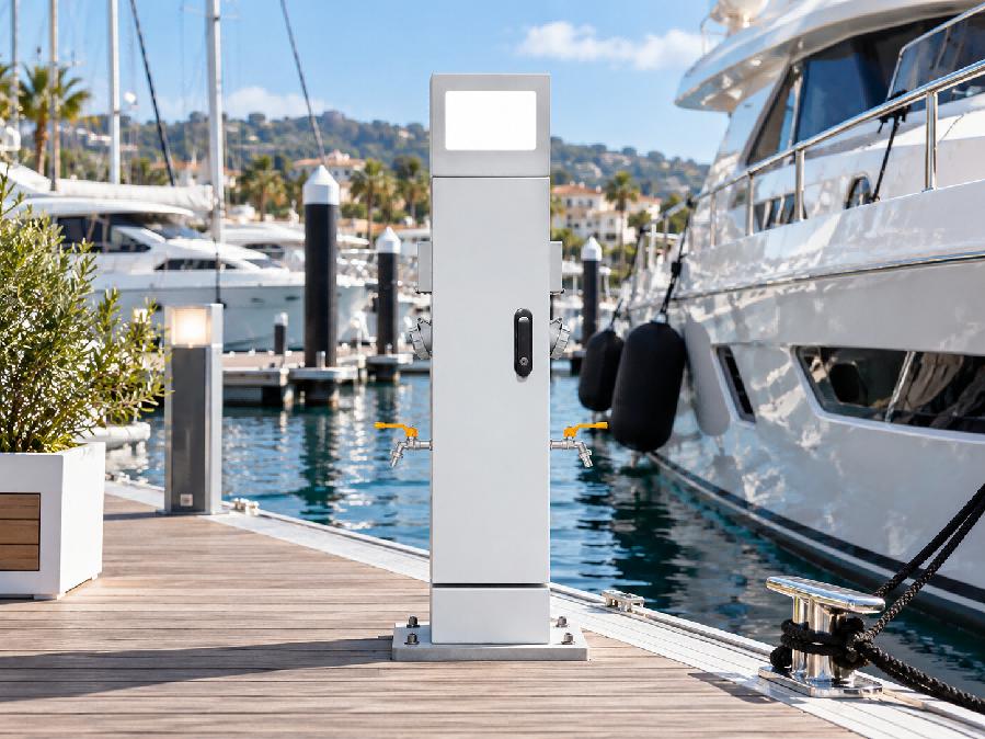
The same reasoning applies beyond campgrounds. Marinas and yacht clubs use the same water and power pedestals on pontoons and quayside berths, and there the dual-sided configuration suits finger pontoons where two berths sit either side of one service position. The electrical protection chain and enclosure ratings discussed above apply unchanged, while the material decision usually shifts towards 316 stainless steel because the installation is directly over salt water. Campground and marina projects therefore tend to specify the same equipment with different material and socket interface selections.
How the Pedestal Is Installed and Verified
Installation involves three stages: confirming site conditions before work begins, determining the mounting method, then handover verification and connection. Each stage produces a decision that is hard to reverse once the unit is fixed in position.
Before Installation
- Confirm the position of the unit relative to both bays and check cable reach from both vehicle positions
- Confirm the internal configuration matches site requirements
- Confirm the supply capacity with both pitches combined
- Confirm the grounding arrangement for the site
- Prepare the foundation or mounting surface
Mounting Methods
Two mounting methods are available. The first is surface mounting, using expansion bolts to fix the unit to a prepared base or slab, with a shorter lead time and no wet trades on site. The second is concrete embedding, where a base is poured with pre-set anchoring provisions and the column is set into it. Surface mounting suits retrofit work and installations where the ground cannot be excavated during the operating season. Concrete embedding gives a more rigid result at new build sites where the civil works are already underway.
Connection and Handover Verification
- Fix the column to the foundation and confirm it is vertical and secure
- Connect the water supply and check for leaks
- Connect the electrical supply in accordance with the site distribution design
- Verify grounding continuity (≤0.1Ω)
- Verify insulation resistance (≥10MΩ at 500V)
- Test the leakage protection device and confirm it operates correctly
- Confirm socket polarity and voltage at each outlet
Differences from Single-Sided Installation
A dual-sided unit changes a few points in the installation sequence, and recognizing them in advance avoids rework. The list below covers the differences an installation team should build into its method statement.
- Positioning is more critical, because the unit serves two bays rather than one
- Cable reach must be verified from both sides, not only from the access road
- The combined load of both pitches must be checked against the supply design and protection ratings
- Only one foundation and one trench are required, which usually shortens the civil program
What the Maintenance Schedule Covers
Maintenance is carried out weekly and monthly, with the two cycles covering different parts of the unit. Weekly checks cover whether the socket protective covers seal properly, the condition of the column housing, whether the lighting and indicator lights operate normally, and the service door lock. These items are visible and quick to inspect, and they are the ones guests notice first when they fail.
Monthly checks cover whether the internal cables are damaged, whether the terminal blocks are discolored, whether the leakage protection test button functions correctly, and internal dust removal. Discolored terminal blocks usually indicate a loose connection rather than a failed component, and catching that condition early avoids a burnt termination later. Testing the leakage protection device on a fixed schedule also builds the record that a safety inspection will ask for.
The schedule should be adjusted to suit the site location, its climate and how often the pitches are used. Coastal sites need more frequent checks of the enclosure surface and seal condition, because salt accelerates wear on those exposed parts. High-use sites need more frequent inspection of the socket covers and door hardware. Recording each inspection with its readings builds a maintenance history that shows whether the unit is ageing as expected.
How the Pedestal Performs at a Tropical Campground
The Huaxi Starry Sky Campground in Xishuangbanna, Yunnan Province, is a useful reference point. Its climate is close to the opposite of a European inland site in every respect that affects outdoor electrical equipment. The project also shows how the additional protection modules are selected.
The campground sits in a tropical monsoon climate zone. The area has high humidity throughout the year, concentrated summer rainfall, frequent thunderstorms and strong ultraviolet radiation. These conditions place three practical requirements on outdoor electrical equipment, in that electrical components must resist moisture over the long term, the equipment must provide lightning protection, and exposed materials must resist UV ageing.

Based on the environmental conditions and operational requirements of the project, JIYA Intelligent provided a corresponding configuration. Twenty GRWE1002020D-R-A water and power pedestals were deployed. In addition to the standard series configuration, environmental protection modules were added for the local climate. Each unit provides four sockets and two water faucets, with leakage, overload and short-circuit protection, and the water and electrical compartments are physically separated within the column.
- Moisture protection module, which addresses year-round high humidity and protects electrical components in the compartment
- Lightning protection module, which addresses frequent thunderstorms and reduces the risk from lightning surges
- High temperature protection module, which includes a thermal protector to keep component temperatures within limits during hot seasons
- Overload protection module, which addresses load fluctuation during peak usage periods at the campground

For the operating model, the campground uses a QR payment system to manage electricity. Water is included in the pitch fee and electricity is metered separately. This operating model has to be configured before the equipment leaves the factory rather than adjusted on site, which is why the decision belongs in the specification stage alongside the electrical ratings. The unified configuration of twenty units also brings operational benefits, in that it produces consistent maintenance procedures, a single type of spare part, and one set of operating instructions for site staff to follow.
Frequently Asked Questions
A dual-sided unit suits twin-vehicle pitches and high-density layouts, reducing the number of foundations, excavation points and service points. Two single-sided units suit sites where pitches need independent service arrangements, separate metering or separate rental terms. The deciding question is whether the two pitches will be operated together or independently, because the equipment choice follows that answer, not the site density alone.
Protection devices follow EN IEC 60898-1 (MCB), EN IEC 61008-1 (RCCB) and EN IEC 61009-1 (RCBO). Industrial sockets follow EN IEC 60309-1 and EN IEC 60309-4, terminal blocks follow EN IEC 60947-7-1, and cable follows EN IEC 60227-3. The full list appears in the protection components table above, and the certificates for a specific project configuration are provided with the technical documentation at order stage.
The protective device rating, the cable current-carrying capacity and the socket rating are matched so that the device operates before the cable is overloaded. The specific ratings are confirmed at the project specification stage, because they depend on the load per pitch and the cable run length. Where several pedestals share a distribution board, the coordination is checked for the group as well as for each unit.
Grounding continuity between the pedestal ground terminal and the site ground electrode is verified at ≤0.1Ω before handover. Installation should follow the applicable local code; at international level, IEC 60364-5-54 covers grounding arrangements and protective conductors. The reading is taken before handover and recorded, so that the verified value is available to the site operator afterwards.
Insulation resistance is verified at ≥10MΩ using a 500V test voltage, measured between live conductors and ground and between live conductors and the enclosure. Each circuit is tested for at least 30 seconds and the readings are recorded as a baseline for later maintenance. A result well above the minimum indicates a dry, correctly terminated installation. A result close to the limit should be investigated before the unit is handed over.
Yes. The GRWE100 series uses a modular socket interface with a 16A-6h 200/346V rating and IP67 protection on the socket, and the interface plate can be supplied to US, EU, AU and UK standards. The socket type is specified at order stage.
The unit is used at marinas and yacht clubs as well as campgrounds, and the electrical protection chain and enclosure ratings apply unchanged. For installations directly over salt water, 316 stainless steel is specified instead of 304 and the moisture protection provisions are confirmed per project. The socket interface is also usually selected to match the vessels and shore power standards in use at that location.
Deciding Between One and Two Pedestals
For campgrounds with twin-vehicle pitches, the value of the GRWE1002020D-R dual-sided pedestal is not simply that it saves one unit. It also reduces repeated investment in foundations, trenching and cable routes across the whole development. It concentrates maintenance at a single inspection point, and it keeps water and power available where the two vehicles actually park. Each of those effects repeats with every twin pitch on site.
The starting point for selection, however, is always how the pitches will be used. If the two pitches require separate metering, separate rental arrangements or independent service capacity, two single-sided units remain the better answer. The comparison table above shows where the difference in cost and site work appears. Where the pitches will be operated together, the dual-sided configuration usually wins on both capital cost and long-term maintenance effort.
JIYA Intelligent has been manufacturing outdoor power distribution pedestals and water and power pedestals for over 20 years, with products available for project-specific customization. Product information across the JIYA Intelligent water and power pedestal range is published on the company website. Project enquiries covering capacity, socket interface and coastal material selection can be sent to the sales team at any time. Site plans and load schedules are welcome at the specification stage, because the coordination detail discussed above is easiest to settle before the equipment is ordered. For further assistance, please visit our contact page.

About the Author
Boda Pan
Engineer, JIYA Intelligent
Boda Pan is an engineer at JIYA Intelligent with five years of experience in outdoor power distribution. He specializes in RV power pedestals, water and power pedestals and marina water and electric pedestals, with a focus on IEC standards compliance.